Most of the electronics in physics experiments is contained in off-the-shelf boxes. However, when new physics experiments are done, the circuitry closest to the new physics is often custom designed and custom built. For this reason, electronics is still taught in the physics program. The quickest introduction to signal conditioning electronics uses operational amplifiers, or "op amps" for short. This month's article samples several of the exercises developed by Dr. Grosh for our Physics 266 course.
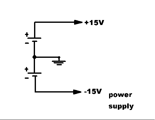 An operational amplifier, typified by the 741 family of operational amplifies, is a high voltage gain, low power amplifier. There are two terminals for the input signal to be connected. There is a single terminal for the output. There are two terminals to connect to a power supply. Typically, the positive power supply terminal is connected to the + side of a 15 V supply, the negative terminal is connected to the - side of another 15 V supply. The other two power supply terminals are connected together, and this point is designated as common, or ground, for the whole circuit. The output voltage is measured between the op amp output terminal and this ground point.
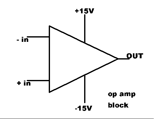
Since modern op amps come in integrated circuit packages, the word "terminal" is outdated; it is replaced by the word "pin." A sketch of the "bare" op amp is shown at right. The input pins are labeled + and -. The significance of this labelling and the (perhaps unexpected) placement of the - above the + will be explained next.
The signal that is connected to the -in pin of the op amp can in fact be either + or - when measured relative to ground. The -in label refers not to the input, but to the output; in the following way: When a positive voltage is established between the +in (negative side of the applied voltage) and the -in (positive side of the applied voltage), then the output voltage will be negative (relative to ground).
For this reason, the -in pin is called the "inverting" input connection.
Similarly, the +in pin is called the "non-inverting" input. If a voltage difference is established between the two inputs so that the positive is on the +in pin (and the negative is on the -in pin), then the output voltage will be positive relative to ground.
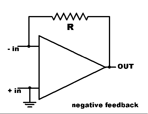
In ordinary operation, the op amp is connected in a way that may be surprising at first. The +in pin (non-inverting input) is connected to ground, and the input signal voltage is connected between ground and the -in (inverting input). With no other considerations, we see that a positive input signal voltage will produce a negative output voltage. The second surprise is the "feedback" resistor, connected between the output and the inverting input. In the figure showing this set-up, the power supply connections are not shown. They are still connected, but showing them clutters the drawing.
Since the output is inverted from the voltage at the -in pin, this circuit tends to suppress the input voltage. That, in turn, tends to drive the output voltage to zero. The resistor prevents the two voltages from being the same: As long as current flows through the resistor, R, there is a voltage difference between the -in and the output voltages. The size of the current through R is determined by the current that flows from source of the signal voltage.
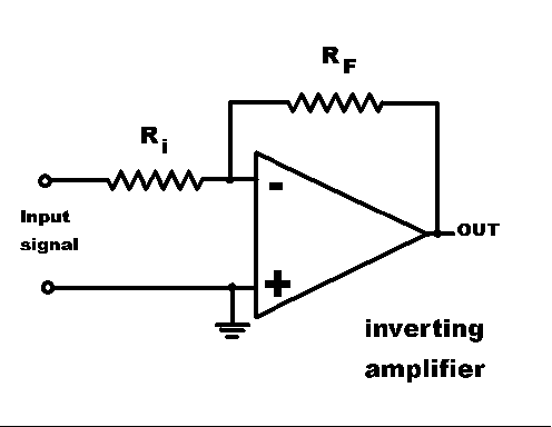
Experimental signals are often voltages. Details of the experimental voltage source are often unknown. For that reason, op amp circuits generally add another resistor, whose function is to produce a predictable current from a given signal voltage. (To do its job, this resistance must be large compared to the output impedance of the source of the voltage signal.) The new circuit is shown at the right. The feedback resistor is now labeled RF , and the new resistor is labeled Ri , for input resistor.
In operation, the connection between output and inverting input forces the voltage at the inverting input to be nearly zero (relative to ground). The input resistor carries a current determined by Ohm's law, and the size of the input signal voltage (relative to ground). The input impedance of the op amp is large, so that essentially all of the current through Ri is forced to flow through RF .
For positive signal voltage, the current flows towards the output pin, and we surmise that the output voltage is lower than the voltage at the -in pin. The size of the difference is determined by the input current and the size of RF . A little bit of algebra (and the assumption that the voltage at the inverting input pin is exactly zero) with Ohm's law shows that
VOUT = (-)( RF / Ri ) VIN .
Adding a capacitor to this circuit has interesting results because the current flowing onto (and off of) a capacitor is proportional to the rate of change (time derivative) of the voltage drop across the capacitor. Placing the capacitor in series with Ri causes the output voltage to be proportional to the time derivative of the input voltage. Placing the capacitor in parallel with RF causes the feedback current to be proportional to the time derivative of the output voltage; that is, the output voltage is proportional to the time integral of the input current and the input signal voltage.
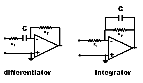
Students test the mathematical character of the output, using sine, triangle, and square wave input. As with many of our labs, they also test the range of validity of the claim made by the name of each circuit: Where does the differentiator fail to differentiate (at frequencies so high that the current is determined by the resistor Ri)? Where does the integrator fail to integrate (at frequencies so low that the current is determined by the resistor RF )?
 An operational amplifier, typified by the 741


