Experiment of The Month
The 19th Century Current Balance With a Sample Intermediate Laboratory Report
In our intermediate laboratory this year, we replaced a measurement with the current balance with one using lasers of four different wavelengths to determine Planck's constant. In terms of the history of physics, we shifted from a 19th century experiment to a 20th century experiment.
The current balance is a sentimental favorite, showing a direct link between the mechanical forces of Newton and the electromagnetic forces of Ampere and Maxwell. In this edition, we pay homage to a grand old experiment on a grand old piece of equipment.
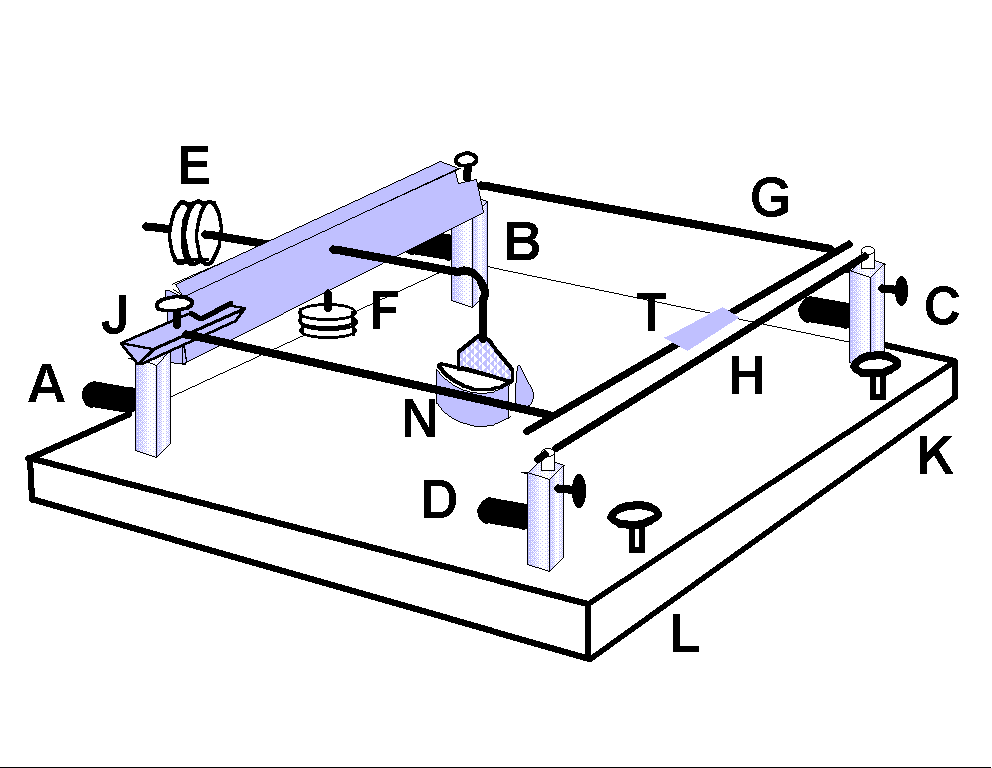
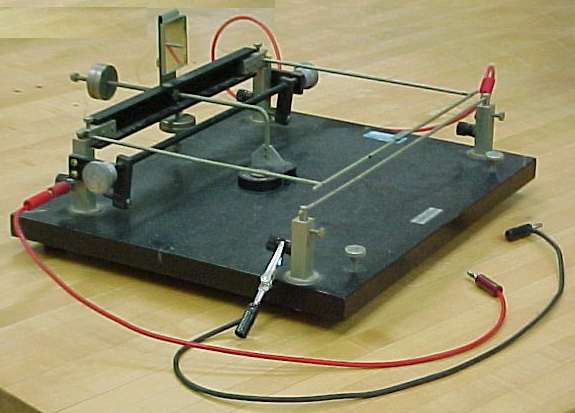
The photograph shows the balance, and the diagram below shows the significant components of this remarkably refined instrument.

We used the current balance to establish the unit of current, the Ampere, by comparing the magnetic force (associated with a pair of currents) with the gravitational force (on measured masses). The two currents are established in the wires labeled G (a ] shaped wire) and H (a straight wire) in the drawing. The important part of wire G is the that which runs parallel to wire H.
To keep the analysis simple, we arrange for both currents to be identical, using terminals A,B,C, and D in the drawing. Current flows in at terminal A, goes around loop G, and flows out at terminal B. From there it flows in a connecting wire to terminal C. From C it flows along wire H, and returns to the power supply through terminal D.
Experimentally there is a force between the two wires, and the force is proportional to the product of the two currents (the current squared in our experiment). In modern terms, the force is caused by the magnetic field of one wire (say H) on the current in the other wire (say G), and has magnitude F determined by the equation
{F}{2 p R} = m 0 i 2 L
where R is the center-to-center distance between wires, L is the length of the wire H, and
m 0 = 4p x 10 -7 {Newton}/{amp2}
is an arbitrary constant which sets the scale for measuring magnetic forces.
In the force equation, once m 0 is defined, everything may be measured mechanically except the current. Thus this equation can be used to establish the size of the ampere using only mechanical measurements. Knowing the meaning of the ampere, in turn, leads to knowledge of the size of a coulomb, based on mechanical measurements.
In this sense, the current balance is the fundamental link between mechanics and electronics. When an unknown current is passed through the balance, mechanical measurements determine the size of the current, in amperes. Because this experiment is passing out of our rotation, it will be described in more detail than usual.
The current balance is built like an old fashioned beam balance. The wire G is supported by two knife edges. (Only one knife edge, labeled J, is drawn; the other is near terminal B. Close inspection of the photograph will reveal both knife edges.) An insulating cross piece joins the knife edges and supports (in addition to wire G) two identical weights (the mass of each is called M here), labeled E and F. We consider weight E first.
E is a pair of large diameter knurled nuts, riding on a threaded rod attached to the crossbeam. When they are in the desired position along the threaded rod, they are tightened against each other, to lock them in place. The purpose of E is to balance the wire G, as well as the rod which bends down to support the flat vane, labeled N.
In operation, the wire G is balanced, within a few millimeters of wire H, with no current applied. Then a current is applied. When the current flows as described above, the direction of the force between the wires pushes G upwards. Weights (in the form of bits of copper wire) are added to the tray T, until the wire G returns to its original position. By measuring the mass of the balancing weights, we determine the magnetic force for that particular wire separation, R. From the force, we calculate the current in the wires.
The remainder of the components work to make the measurement efficient and accurate.
The set screws in posts C and D allow adjustment of the wire H, to make it parallel to the matching segment of wire G.
The screws K and L go through to contact the table on which the balance sits, and serve to make the balance level.
The mirror atop the beam (photograph only) is used to determine the angular position of the balance. A horizontal laser shines on the mirror and is reflected upward because of the slight tilt of the mirror, controlled by a screw behind the mirror. The location of the laser spot on a distant screen is a good indicator for judging the return of the balance to its original position, after weights have been added. Note that if the balance changes angle by and amount @, then the angle of reflection of the light beam changes by an angle 2@
 In practice, it is convenient to place a small weight on the tray which brings the balance nearly to the zero-current condition, and finally, to adjust the current as a fine adjustment to zero-balance.
The weights F are of the same construction as the weights E, but with a different purpose. In the absence of weights F, when the weights E are set correctly, the beam is in balance, with its center of mass somewhat above the axis of rotation. If the center of mass is at the same height as the knife edges, or above, the balance will be unstable; a small angular velocity will continue until the balances falls off the edges.
Weights F, a distance D below the axis of rotation, move the center of mass below the axis of rotation, with two purposes:
- They provide a restoring torque which pulls the balance to a well defined equilibrium point. (It is easiest to visualize, but not necessary, if we think of the weight F being directly below the center of mass at equilibrium.) Shortening D decreases the restoring torque and makes it easier for a small current to cause a large change in the separation of the wires G and H. Lengthening D increases the restoring torque, and makes the balance less sensitive to friction at the knife edges.
- The distance D from F to the axis of rotation determines the natural frequency of oscillation of the balance, as follows: The usual simple harmonic motion arguments tell us that the square of the angular frequency is equal to the moment of inertia, I, divided by the maximum restoring torque:
w 2 = (DMg)/{ I}
The moment of inertia includes the moment MD2due to F, but is dominated by the moment I0due to the beam, to E, G, and to the vane at N. The effect of this dominance is that shortening D *lowers* the frequency of oscillation (contrary to shortening the length of a simple pendulum).
The vane near area N is aluminum, and passes freely between two magnets, facing so that they produce maximum magnetic field in the aluminum. Eddy currents are induced by motion of the aluminum through the magnetic field. The electrical resistance of the aluminum to the flow removes energy from the motion of the aluminum. That is, the oscillation of the pendulum is damped by the eddy current effect.
With the current through the balance determined from the weight of the bits of wire, that same current passes through an uncalibrated ammeter. The indication of the ammeter is labeled with the known current. The current is changed and the balancing process repeated, leading to a calibration table for the ammeter. In the end, the ammeter is calibrated using the force of gravity.
Lab Report Based on Current Balance
As an aid to our junior physics majors, the following is a sample laboratory report for the intermediate laboratory, using the current balance as the apparatus. The following is not meant to be an example of perfection, but an example of one report format that works.
Calibration of an Ammeter
John W. Dooley
January 15, 2003
Abstract
The calibration of an ammeter has been checked using the current balance. The current balance measures current by measuring the force between two parallel wires carrying that current. It provides the connection from Newton's laws and the gravitational force to the Ampere, and hence, to the Coulomb. The slope of ammeter reading versus measured current should be 1. In our experiment, it was 1.052 with a standard deviation in the slope of .009. Uncertainties in two distances, in 9 masses, and in settings at balance lead allow the possibility that the ammeter correctly calibrated.
Introduction
 The project was to use the current balance to calibrate an ammeter, both supplied, along with a low-voltage high-current power supply. 20 generations of physics majors, working before me on this project, aided in my understanding of how to do it. The 10 Amp scale on the ammeter was used. The smallest division is 0.1 Amp, and the device has a mirrored scale to aid in interpolation.
The current balance is shown in the figure at the right. The labels will be used as references in describing the operation of the balance.
The current supply is connected to posts A and D. Current flows through knife-edge J into a U shaped wire, labeled G, and exits through an unlabeled knife edge near post B. An external wire connects post B to post C, so that the same current flows along the lower wire (labeled H) before returning to the power supply at post D.
The right most segment of wire G is suspended above wire H. With the currents arranged as above, the magnetic interaction between G and H causes a force which tilts G (and its supporting beam) up, pivoting on the knife edges.
Not shown in this figure is a mirror mounted on the bar which supports items E and F. A laser is reflected from this mirror, and the position of the laser spot on a distant wall is the indicator for the angle of the balance. Small masses are added to the trough, T, to bring the laser spot back to the zero-current position (with no weights) When this is done, the distance between the wires is the same as it was with no current, and the weight of the masses has the same magnitude as the force between the two wires.
The force between the two wires is typically (See "Physics for Scientists and Engineers," third edition, by Douglas Giancoli, Prentice-Hall, 2000, pages 710 to 712 for a nice discussion) described in terms of a magnetic interaction. However for this lab all we need to know is the expression for the force, F:
{F}{2 p R} = m 0 i 2 L
where R is the center-to-center distance between wires, L is the length of the wire H, and
m 0 = 4p x 10 -7 {Newton}/{amp2}
is an arbitrary constant which sets the scale for measuring magnetic forces.
All quantities except current are measurable with the current balance, so that the current magnitude may be determined from measurement of the balance.
The Experiment
The balance was leveled using a bubble level on the platform, by adjusting screw legs K and L. Since the balance sits on 4 feet, the two feet at the back required shims (a mouse pad in one case and copper shim stock in the other) in order to level the platform.
The two magnets (N) were set 2 mm apart, so that the aluminum vane moved between them without touching when the balance changed angle. Eddy currents induced in the moving vane by the magnets extracted energy from the moving balance; the vane acts as a damper to the simple harmonic motion of the balance about equilibrium. With this gap, the balance took about 10 seconds to come to rest.
A pair of nuts, E, are moved along their threaded rod to adjust the balance. E was set so that (with no current) a gap of 1mm (with an uncertainty of 0.2mm) appeared between G and H. Both wires were bent slightly, and H was adjusted vertically at post D so that the two wires were parallel within .2mm. When the E nuts are incorrect position, they are tightened against one another so that they do not move during the experiment. The diameter of each wire, G and H, was 3mm (with an uncertainty of 0.2 mm) so that the center-to-center distance between the wires was
R= 4 mm with an uncertainty of 0.4mm.
The length of the part of G which carried current above H was between 26.5 and 26.0 cm. Calculations used 26.3cm, with an uncertainty of 0.2cm. All of these distances were measured with a ruler whose smallest gradation was 1 mm.
In this condition, the laser beam was reflected from the mirror to a wall 5 meters away. The beam was adjusted so that it was essentially horizontal, by adjusting the angle of the mirror. (The mirror is not shown, but sits atop the beam held up by the knife edge J and its opposite number.) At the wall, a piece of masking tape was placed on the wall, in the path of the laser beam. A circle was drawn on the tape, around the circumference of the beam spot. When weights are added to bring the current-carrying wires back to the zero current direction, the spot returns to this circle.
The current adjustment was rather coarse, so that the spot sometimes missed the circle by 1 mm; too high by 1mm for one current setting and too low by 1mm for the adjacent current setting. At high currents (6 or 8 Amp), this made an uncertainty of about (+/-) 0.15 Amp in the correct current for balance.
Nuts F were adjusted about half way along their threaded rod. Raising them moves the center of mass closer to the axis of rotation. Thus raising F lowers the energy required to make a small rotation about the axis. Raising F makes the balance move farther for a given force from the currents. That is, raising F increases the sensitivity of the balance.
With F in the half-way position, the balance responded not only to the current and the small masses, but also to air currents and to people leaning on the table or walking by. In the half-way position, it was difficult to keep the spot on the wall still, but possible. This was the chosen balance between sensitivity to current and sensitivity to external noise.
Changing F also changes the natural frequency of oscillation of the balance when perturbed. As set, the natural oscillation had a period of about 2 seconds.
The small masses to be added to the trough were prepared as follows: 3.5 cm of stranded #20 wire was cut from the spool, and the insulation removed. The mass of this segment of wire was 0.17 grams with an uncertainty of .005grams (fractional uncertainty of .03). There were 10 strands in the sample, so each strand had a mass of 0.017 gram. One of the strands was cut in half (0.0085 gram), and one of the half was cut again, to make a pair of strands 1/4 of the original length (0.0043 gram).
To make a measurement, a mass was added to the trough, and the current was increased until the laser spot returned to the original position. The mass was recorded, and the reading of the ammeter was also recorded. The results are compiled in the two bold-faced columns in the table below.
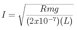
The first three columns of the table show the mass (m) on the trough, the weight (mg) on the trough, and the current (I). The current is calculated from

The error in I caused by errors in the measured quantities is calculated by first calculating the differential of I:

With our expression for I, this becomes

The size of the error in each quantity has been estimated above, but the sign of the error is unknown. In the worst case, each error causes a deviation in I with the same sign. The worst case deviation can be calculated by taking the absolute value of each term in the differential:

Written in terms of individual errors, this gives a fractional error in current of

With the values in this experiment, the fractional error in current is 0.07.
Calibration Curve
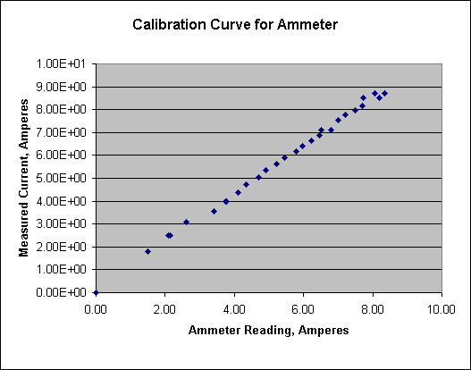
 The calibration graph is a plot of measured current versus ammeter reading. If the ammeter calibration is correct, the slope of this graph will be 1, and the intercept will be zero. The graph for this set of measurements is shown at the right.
Using the Linest function in Excel, the slope is found to be 1.052 with an uncertainty of .009. The intercept is .12 with an uncertainty of .05.
At the highest current, the estimated error of measurement is about 0.6 amp. If the data are increased to the lowest measured current allowed by the error estimate, the slope of the line would be decreased by 7%. Thus the measurement allows the possibility that the ammeter calibration is correct in slope.
The intercept is significantly different from zero. It is probably relevant that the difference becomes insignificant if the lowest three current measurements are removed from the calculation. This that case, the slope is 1.06 with an uncertainty of .01, and the intercept is .01 with an uncertainty of .06.
As noted in the table, the first three currents were measured with the laser spot in a slightly different position at balance. It is anticipated that if the low current measurements were repeated, the ammeter would be found to be well calibrated.