Experiment of The Month
Laser-Drilled 10 Micron Holes
Our labs do not have written instructions. In keeping with this spirit, the description given here will be brief and general. The intent is that each performance of the lab will be unique; in each nature will reveal a slightly different face to the observer.
In this senior seminar project Anthony Jackson aimed to focus a laser beam to a spot small enough to drill holes 0.01 mm in diameter. He succeeded, and in the process did a nice bit of physics: There is a rule, well known in optical laboratories, that to make the smallest possible spot, the lens should have the smallest possible focal length. Neither Mr. Jackson nor his advisor knew this rule, but Mr. Jackson worked it out analytically. In doing this, he crossed the line from doing technology to doing physics.
The aim of a senior seminar project is not necessarily to do physics that has never been before. Rather, it is to do some physics as if it had never been done before. For a senior project it is ok to re-invent the wheel if, in the process, you learn something about how to invent. After looking at several analytical discussions of spot size, Mr. Jackson decided to do it his own way. He developed a derivation of diffraction by a single slit that worked nicely to describe a focused beam of light. The derivation follows:
The derivation for the diffraction pattern from a slit begins in an ordinary way, with this figure laying out the parameters:
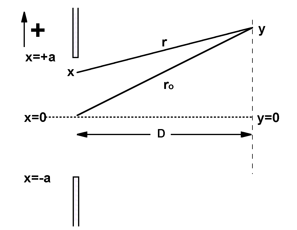
We assume that an electromagnetic plane wave travels from left to right, passing through the slit centered on x=0. Each small bit of space in the slit acts as a radiator, following Huygens' principle. Each bit is identified by its location, x. The electric field at location y is the sum of the electric fields originating from each of the bits within the slit. The difference in travel distance between the paths labeled r and ro determines the relative phase of the waves that add after traveling along the two paths.
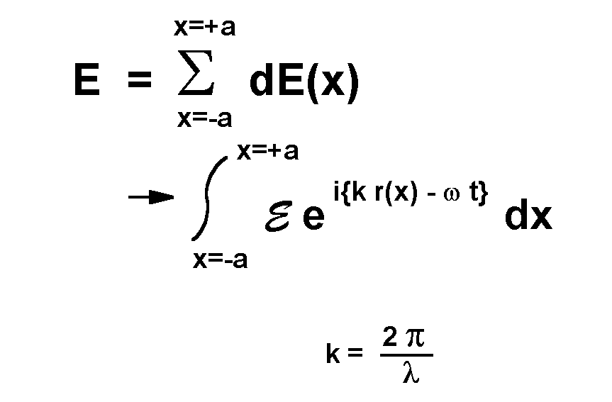
That sum can be written as an integral over the slit, with the electric field determined by the standard complex representation of a traveling wave. Note that the distance r in the wave expression is a function of x. Because the interference depends on the differences in distance traveled by the wave, the integrand is re-expressed in terms of that difference, r - ro . In addition, the time dependence is factored out of this integral over space.
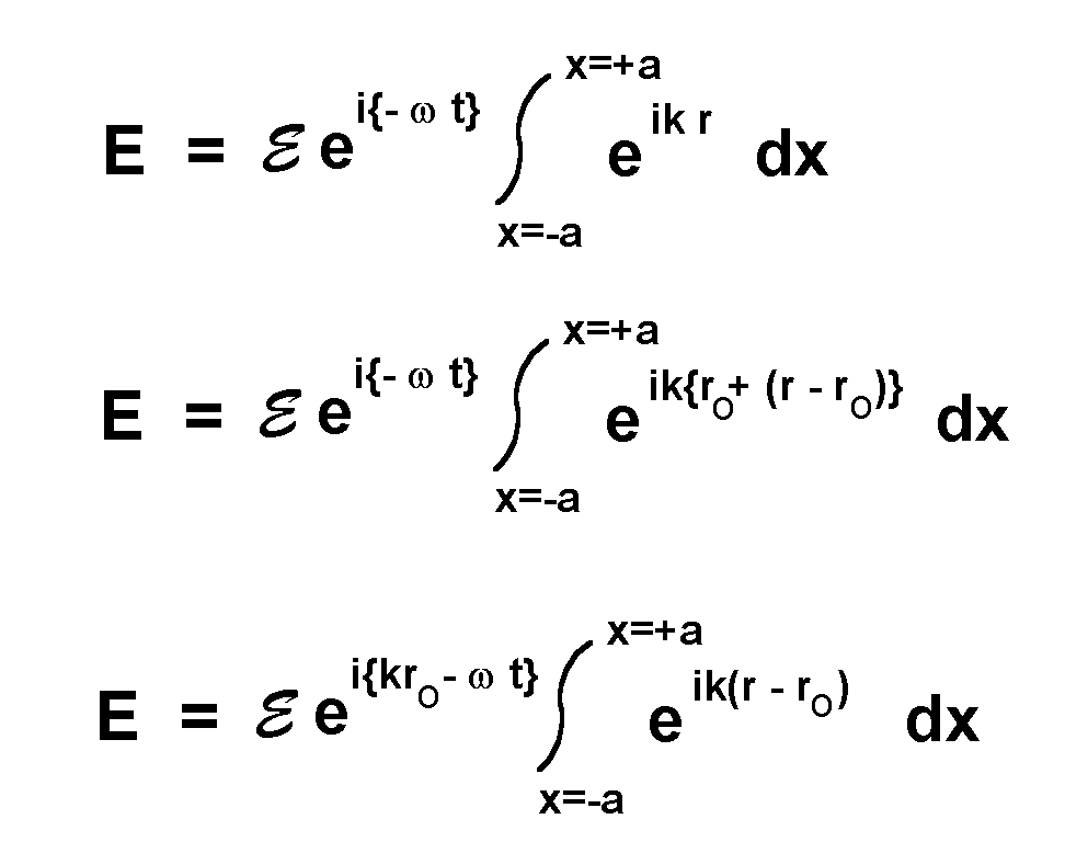
It is in the calculation of r - ro as a function of x that Mr. Jackson's derivation rises out of the ordinary. He calculates the difference using the Pythagorean theorem with the geometry of the first figure:
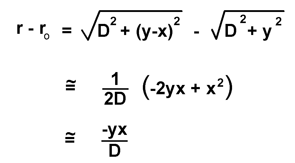
The square roots are expanded using the usual assumption that D is large compared to other distances. The final step requires the additional assumption that x is much less than y. This expression for r - ro is plugged into the integral, and the result is a time varying electric field, with amplitude Emax given by
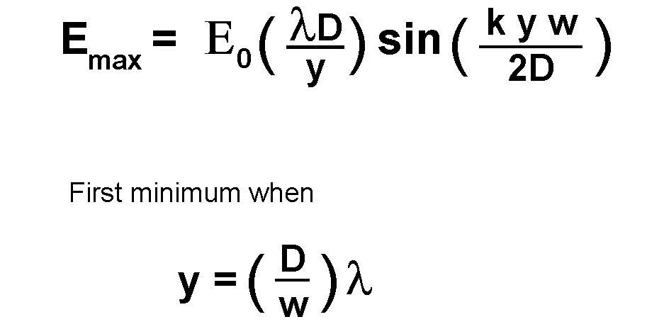
Where E0 is a constant. Emax is greatest when y=0, and Emax is zero when the sine function reaches zero. The value of y which first drives Emax to zero is taken as the size of the central diffraction spot.
This is a standard result. The payoff for using this particular method of calculation comes when the light coming through the slit has been focused to a spot, as sketched below.
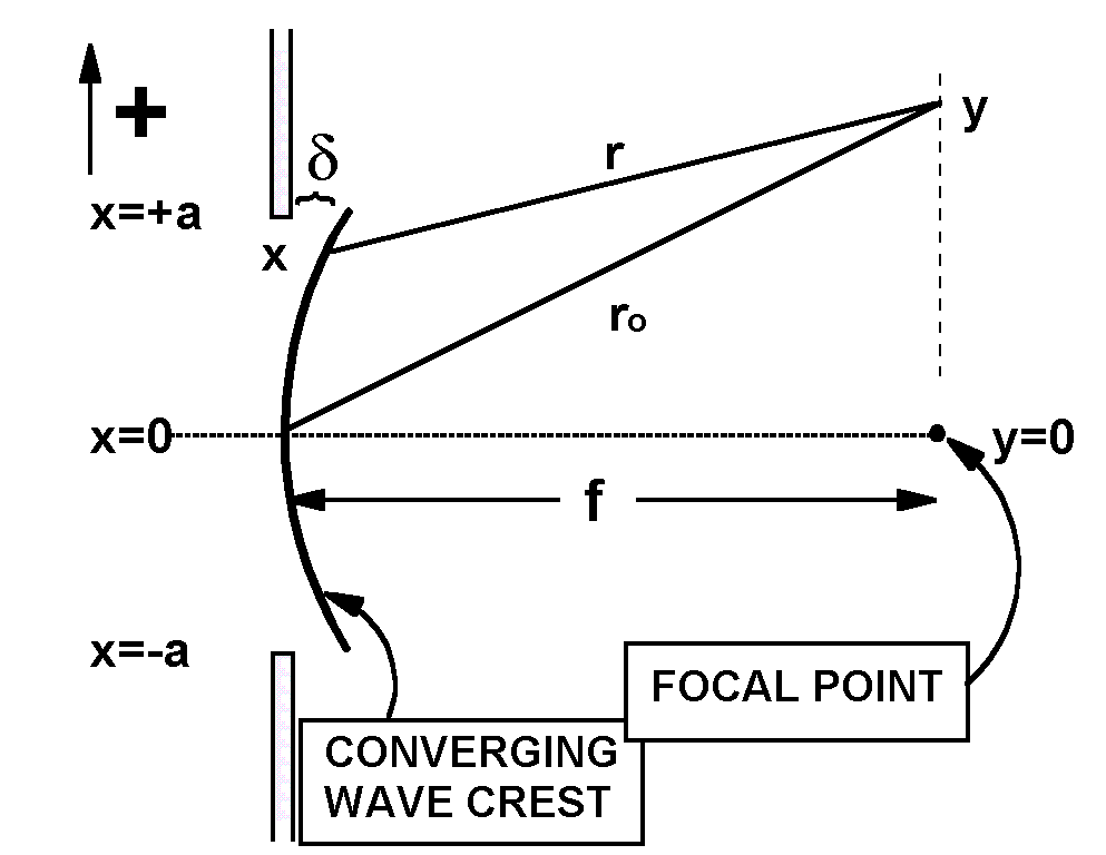
The focused wave is not a plane wave. In our geometry a wave front is a cylinder collapsing towards the focal point. One such wave crest is labeled in the picture above. Now light from different parts of the wave crest still arrives at point y, and combines by superposition. Now, however, the ray from location x starts a little farther to the right, by a distance labeled d (delta).
In the diagram, the distance D has been renamed "f" because that distance is the focal length, if the lens is pressed against the left side of the slit. The calculation for r is changed slightly because the base of its right triangle is shorter by a distance d (delta). Since every point on the wave front is now a distance, f, from the focal point, we can calculate d (delta) from a triangle with f as the hypotenuse, x as the vertical leg, and f-d as the base.
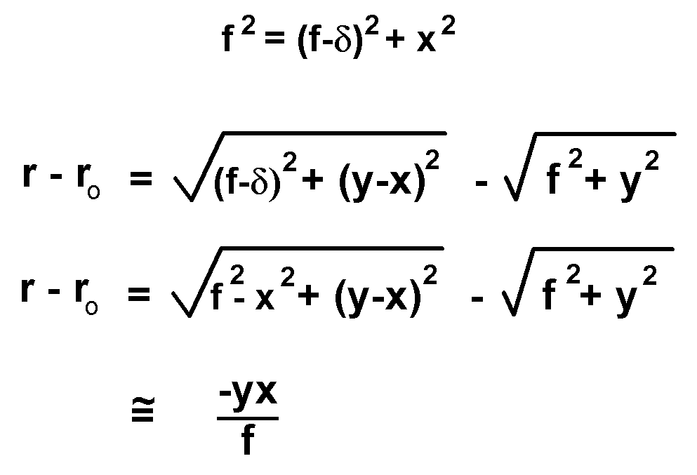
The second two equations above calculate the difference in path, as before, except that the base of the triangle is reduced by d (delta). When the square roots are expanded, the extra term has the effect of eliminating the x2 term. The final result is accurate even if y is not large compared to x. This improvement is accuracy is made visible by Mr. Jackson's method of calculation.
The difference in path has exactly the same form as for the slit, so we conclude for the focused beam:
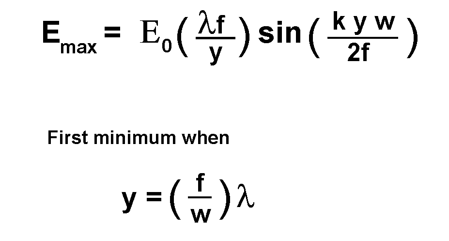
The upshot of this result is, for small spot size (small y), all other things equal, make the focal length of the lens as small as possible.