Experiment of The Month
Generating Surface Plasmons
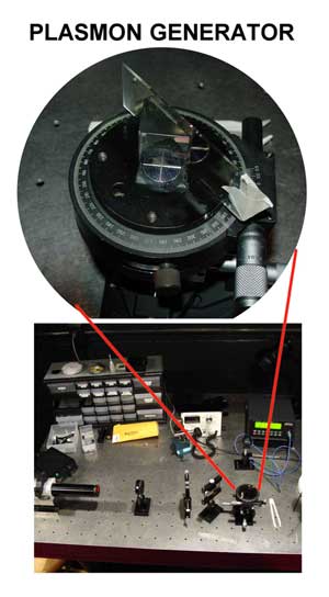 Seniors Leah Gallek and David Saint John are working with Dr. Natalia Dushkina to generate surface plasmons and use them as a probe for the optical properties of new materials. Leah presented a paper on the subject to the annual meeting of the Central Pennsylvania Section of the American Association of Physics Teachers on April 8, 2006. On the same day, David presented a poster at the Millersville Undergraduate Student Research Conference.
The apparatus used is in the figure at the right. Light enters the prism, traveling upwards in the photo. It strikes the base of the prism at an angle controlled by the micrometer at the lower right of the enlarged section. A special coupling fluid allows light to travel through the microscope slide attached to the prism base. The microscope slide effectively becomes the base of the prism.
The surface plasmon travels on the free surface of a thin (60 nm) film of silver that is placed on the far side of the microscope slide. This side is "free," in contact with the air. (The film was fabricated with the department's vacuum deposition system.) Light strikes the base at an angle chosen so that the light is totally reflected.
In this situation, an evanescent wave is also created, extending beyond the surface of the free side of the microscope slide and the silver film. This wave in turn couples to the free side of the metal film and generates a plasmon wave in the film, propagating along the free surface. The usual material for both prism and slide is "BK-7" glass.
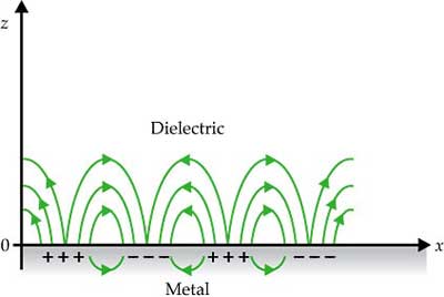
A surface plasmon can be pictured as a traveling charge density wave on the surface of a metal. At a wave crest, electrons bunch, being pulled towards a trough by positive ions that remain in place. The charge density wave is somewhat reminiscent of a longitudinal pressure (sound) wave in air. The figure below, from Ebbesen et.al in Physics Today, May 2008, shows the charge distribution and the accompanying electric fields.
Because the plasmon includes a longitudinal wave character, the incoming light wave is polarized, with its electric field oscillating in the incident plane, defined by the light velocity vector and the normal to the base of the prism. This electric field has a component parallel to the base of the prism. The figure shows a HeNe laser on the left. Its light beam passes through a polarizer to be sure of the polarization before entering one face of the prism.
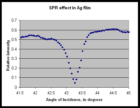
After reflecting, the light beam exits the other face of the prism and its intensity is detected. When plasmons are generated in the metal film, energy is withdrawn from the beam. The presence and nature of the plasmon is deduced from the resulting dip in the reflected signal strength.
After the incident angle is made large enough to establish total internal refection, the hunt for plasmon excitation begins. The light is "tuned" to generate plasmons by carefully changing the angle of incidence of the light onto the bottom surface of the prism. When the pattern of the light falling on the bottom surface matches the plasmon in both frequency and wavelength, a plasmon is generated. The plasmon velocity at the free surface is higher than for the surface bound to the prism. The plasmon wavelength at the free surface is long enough to match optical wavelengths.
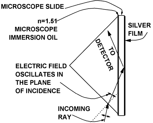
Incoming ray refracts at air-prism interface and totally reflects at the microscope slide.
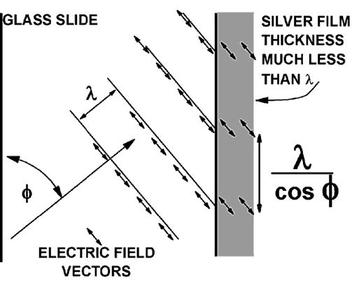
Evanescent disturbance wavelength matches to plasmon wavelength, both at the optical frequency
The silver film is thin compared to the light wavelength so the evanescent electric field penetrates the silver, as sketched above. By changing the angle f, the wavelength of the disturbance in the silver is adjusted to match the plasmon wavelength at the optical frequency.
The plot below shows relative reflected light intensity as a function of the angle of incidence of light on the prism base. The frequency of the HeNe laser light is 4.7x10¹⁴ Hz. When the separation of light wave crests on the prism base matches the plasmon wavelength at the same frequency, a plasmon is generated and the reflected light shows the characteristic dip in intensity. In this experiment, total reflection began at about 41.0 degrees.
Professor Polman at Utrecht University and Professor Kojima at Rutgers University have useful tutorials on the subject.
When light enters a transparent dielectric material, a disturbance propagates through the material that is a combination of electromagnetic and electronic waves. The electrons are bound to atoms, and oscillate without significant energy loss in sympathy with the electromagnetic wave, the displacement proportional to the electric field. Their mass slows the progress of the disturbance.
Some Background Thoughts:
When light emerges from the material, it is "late" and we say that light traveled slowly in the dielectric. If the dielectric material is opaque, the oscillating bound electrons convert their energy to heat. We say the light is absorbed by the material.
When light strikes a metal, ordinarily the electrons respond in the usual resistive way; the velocity of the conduction electrons is proportional to the electric field. They move to reduce the electric field, driving it to nearly zero, allowing a very short penetration distance.
The conduction electrons are resistive because as they move they colide with ions in the metal and lose kinetic energy to heat. The average time between collisions varies with the metal and the temperature. If the light frequency is high enough, the electric field reverses before most electrons have a chance to collide.
In this situation, the acceleration of the electrons is proportional to the electric field. This means that the displacement of the electrons is proportional to the field, but opposite to the displacement that an electron in a dielectric experiences. Since the dielectric electrons act to reduce the electric field strength inside the material, the conductions in this special situation act to increase the electric field in the metal.
The metal is said to exhibit negative dielectric constant at these high light frequencies. The result is a much stronger electric field at the free surface of the metal in the plasmon generator. The electric field due to the evanescent light is enhanced and couples strongly to the surface plasmon.