Experiment of The Month
Intermediate Laboratory Sampler
The MU Physics Department does not claim to have invented these labs. The origin of these labs is currently unknown to us. Our labs do not have written instructions. In keeping with this spirit, the description given here will be brief and general. The intent is that each performance of the lab will be unique; in each nature will reveal a slightly different face to the observer.
The intermediate laboratory is typically taken by junior physics majors in the fall semester. This fall, students were presented with four pieces of equipment. Their task was to figure out how the equipment worked, and to use it to investigate some interesting physics. During the semester each of the 12 students worked on each piece for a few weeks, in a sort of "round robin scramble" sequence. They wrote reports and left the report behind for the next pair of students to use as a "leg up" on their study.
These students have moved up the "responsibility gradient" in their laboratory experience. They are not lectured on what should happen, or how the equipment works, although the team of two teachers circulates, giving enough hints to keep things moving forward. The descriptions that follow are even more skeletal than
Selected comments from this fall's students are included, in boldface type.
MICHELSON INTERFEROMETER
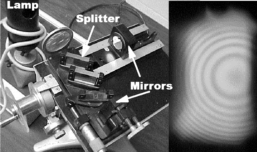
Students first hear of this famous device in classroom discussions of modern physics. They know that the idea is to split a light beam into two; send the two beams along two different paths; recombine the beams and observe the resulting interference pattern. The device can be used to measure the wavelength of light. The first problem is to adjust the mirrors to make the interference pattern appear. The second problem is to understand the rather complex shape of the interference pattern. The inset shows the circular pattern that can be made to appear.
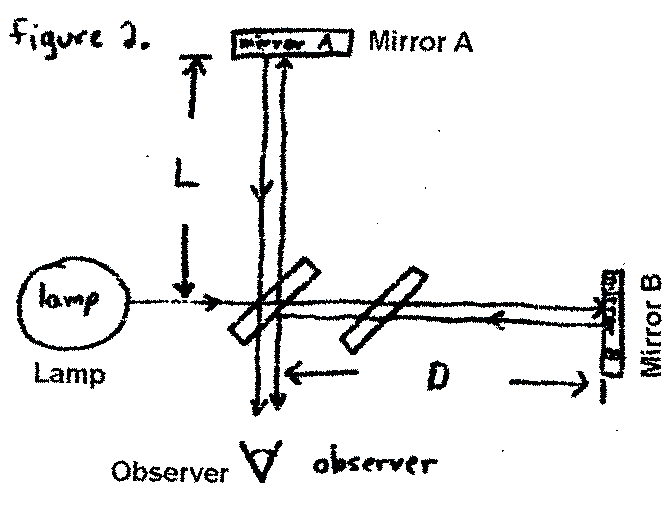
The figure below shows a student's sketch of how the light splits and recombines to cause the interference pattern.
GEIGER COUNTER
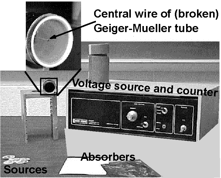
This device was the workhorse detector in the middle years of experimental nuclear physics. Students find one knob to adjust and a "scalar" which counts (displays one integer after another, in sequence 1,2,3,4,5....) when it is connected to the terminals of a gas-filled cylindrical capacitor. Students determine what controls the rate at which the scalar counts, and what the optimal setting of the knob is. They observe remarkable variation in the results of identical
[Initially,] in order to understand what was happening here, we simply did small experiments with the samples using the timer and the counter... When we place a sample under the detector and set the timer for a certain time and turn the counter on , we see the display of the counter begin to increment, or "count." [The rate of counting] depended on the sample and also on the way in which the sample was oriented (number on face up or down).
We then began to place [obstructions] in front of the detector, immediately noticing a decrease [in the count rate compared to] that sample with no obstruction. As the obstructions became
"PILLAR OF LIGHT"
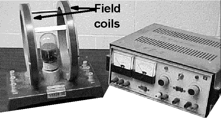
Students are presented with this glass tube, a power supply, and a wiring diagram with suggested voltages. When they hook it up, a glowing vertical pillar appears in the center of the tube. Their task is to discover how to perturb the pillar, and how to interpret the pillar's response to
After a couple of minutes we saw a bluish-purple "beam" coming through the plate and going straight up and hitting the top of the tube. The DC field voltage was zero as was the grid voltage, and the plate voltage was set at about 100 volts. We the n adjusted the plate voltage and noticed that if we decreased the plate voltage the beam would get less intense and if we increased the plate voltage the beam would get more intense.
When we increased [the field current] the beam curved into an apparent circular path.
"CURRENT BALANCE"
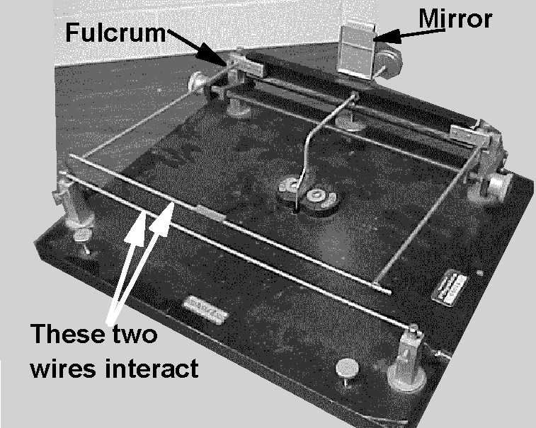
Students have encountered the idea for this experiment in General Physics II: When two current-carrying wires are placed near each other the wires experience a sideways force. The force can be either attractive or repulsive, depending on the details of the set-up. A measurement of this force can lead, with some analysis, to a value for the current flowing in the wire. In fact, this device produces the traditional operational definition of the Ampere, and hence the Coulomb. The device has a wondrous number of adjustable pieces. A major problem here is to figure out the purpose of each, in terms of the effectiveness of the current measurement. The official goal in this exercise is to calibrate an ammeter using this fundamental determination of current.
By adjusting the counterweights of the top rod, we set the equilibrium of the top rod at a distance r above the stationary one. Adding a mass directly to the top rod will move its equilibrium position down... This method can be used to fin d the current in the circuit [using the equation]

