Experiment of The Month
What Holds a Car Up?
Senior Brett Kunkle, who will teach high school physics after his National Guard commitment, wanted to study the forces in the sidewalls of a race tire for his senior seminar project. As often happens, the physics led on a slightly different path. The question of identifying the forces that hold up a stationary car turned out to be the focus of his project.
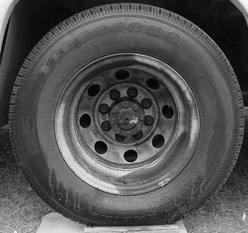
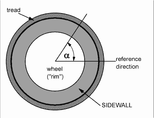
The figures show a real tire, and a stylized sketch, with parts named. The angle alpha will be used to identify different locations around the wheel on the tire sidewall.
Brett focused upon the forces by the rubber tire on the metal wheel (the "rim") and used the following model for the tubeless tire: The tire pressure causes tension in the sidewall so that the sidewall pulls away from the center of the wheel. Since the tire is fastened to the rim, the sidewall pulls on the rim, pulling away from the center of the wheel.
When the car jacked up so that the wheel does not touch the ground, the sidewall pulls radially outward with equal strength, all the way around the rim. The net force on the rim is zero. In particular, the upper half of the tire pulls up, and the lower half of the tire pulls down, and both halves pull with the same size force.
When the wheel rests on the ground, there is now an extra force on the rim: The force by the axle of the car, pushing down on the rim. Since the system remains at rest, it must be true that the net force on the rim is zero. The force distribution by the rubber tire on the rim must have changed from the situation before. Now, the sum of the forces by the tire plus the force by the axle must add to zero. We know that the force by the axle is downward, with a size roughly equal to 1/4 the weight of the car.
The result is that, under load, the upper half of the tire pulls up more strongly than the lower half pulls down. The story of how this comes about is the kernel of Mr. Kunkle's report.
He was guided as he began by a thought experiment which Dr. Miziumski proposed during the first seminar presented by Mr. Kunkle: A small frog sits on a large soft balloon. What forces hold the frog up? The answer is that the frog makes a depression in the balloon surface. The tension in the wall of the balloon at the rim of the depression produces a vertical force that "balances" the force of gravity on the frog. (The pressure in the large balloon does not change significantly when the frog hops onto it.)
This train of thought has an ancient pedigree: Galileo (e.g. in http://www.globusz.com/ebooks/HistSci2/00000016.htm) worked on the problem of how a thin piece heavy material (such as a razor blade) can float on water. He noted that the material depresses the water, but did not quite reach the idea of surface tension, pulling upwards along the rim of the depression.
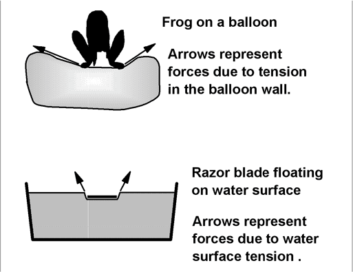
Brett did measurements and calculations to determine if such a simple tension-based model could account for the forces that hold the car up. It turned out that the model fits rather well.
The figure at the right shows a cut vertically through the tire and wheel. Only the top half is shown, with the top tread, and the upper part of the wheel rim visible. If the axle were shown, it would run horizontally, left to right.
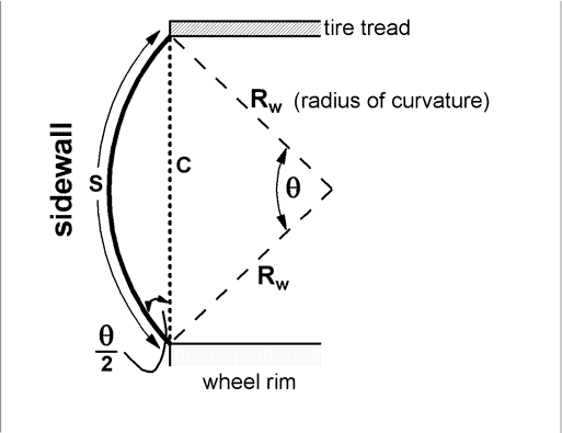
The tire has a side wall that is regarded as flexible. The force by the sidewall on the wheel rim is a tension force, with the force vector lying in the sidewall, pulling away from the rim. For the part of the rim that is shown, this force has a large vertical component. The angle between the sidewall force and the vertical is called @/2 in the figure, where @ is the keyboard representation of the Greek letter theta.
The sidewall is assumed to be curved in a circular arc. The radius of the circle onto which it fits is Rw, and the length of the arc is the length of the sidewall, S. The vertical dotted line in the figure is the chord, C, associated with the arc S. The angle @ in radians has magnitude S/(Rw).
In our macroscopic physics course, a useful result is presented: The tensile stress Syy in the side wall is related to the pressure, P, in the tire and the radius of curvature The equation is Syy = (P)( Rw)/W, where the y direction is along the arc labelled S in the figure, and W is the thickness of the tire sidewall.
Consider a strip of side wall of thickness W, running a distance, S, from the tread to the wheel rim. We call the width of the strip D. This strip acts like one spoke in an ordinary bicycle wheel. The force by this strip on the rim has magnitude
dF = (Syy)(W)(D) = (P)( Rw)(D)
The net force by the side wall will be sum of the forces of all these strips. The notation dF anticipates that we should integrate the wall force all the way around the wheel to get the force by the wall on the rim.
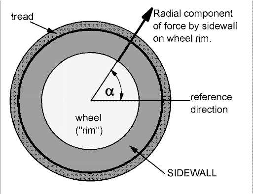
Forces by the sidewall which point perpendicular to the wheel (parallel to the axle) are important for turning the car, but not for holding it up, at rest. Two steps are needed to find the vertical component of the force by the sidewall on the wheel. First, we calculate the component of the force dF along the chord C in the figure above. This is called the "radial" component and is sketched at the right.
dF radial = dF cos {@/2}
The second step for finding the vertical component of the force by the sidewall on the rim is to calculate the vertical component of this radial force.
dF vertical = (dF radial) sin {alpha} = (P)( Rw)(D)(cos {@/2})(sin {alpha})
Qualitatively, looking at the photograph of the tire, we see that the sidewall "bulges out" more on the bottom side of the wheel. On the bottom side of the wheel, the radius of curvature is smaller, and the angle @ is larger. Both effects reduce the vertical component of the force by the sidewall on the rim on the bottom side of the wheel.
Thus the top half of the sidewall pulls up with a vertical force that is stronger than the downward vertical force by the bottom half of the sidewall.
For his senior seminar project, Brett Kunkle measured the chord C, and the maximum distance between the arc S and the chord (with a piece of apparatus that he built for the purpose) for a family of points around the tire of his own car. From the measurements, he determined the radius of curvature of the tire, at each point around the circumference. Using the measured gauge pressure in the tire, he calculated the force by the tire on the wheel. His results were satisfyingly close to 1/4 the official weight of his car.
For purposes of this page, we can use three pieces of data plus the photograph of a tire shown at the top to test the model. We take the tire gauge pressure to be 3 atmospheres (45 psi or 300 kPa). We take the diameter of the outer part of the wheel rim to be 46 cm (18 inches). We take the length of the sidewall from rim to tread to be about 14cm. This length is S, the arc length, all the way around the rim. (We assume that the wall does not stretch significantly).
Referring to the photograph, we can determine the chord length C by measuring it on the photo. Then, using the ratio of C to the diameter of the rim (as measured on the photo) and the given "actual" rim diameter, we can find the chord length. Knowing C and S, we can calculate the ratio C/S. For convenience we give the ratio a name: L=C/S. Using L, we can find the radius of curvature as follows:
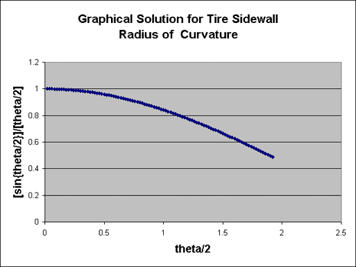
Trigonometry tells us that sin{@/2}=C/(2Rw) and with the angle is in radians, we also know that @/2=S/(2Rw). This means that L = [sin{@/2}]/[@/2]
A graph of [sin{@/2}]/[@/2] versus @/2 can be used to discover the value of @, after we have the value for L from our measurements.
With @ and the arc length, we can find Rw=S@, and finally the vertical component of the force by a strip of tire (of width D), using
dF vertical = (P)[S@](D)(cos {@/2})(sin {alpha})
The graph, and a table of calculations for several values of alpha are shown below. Negative values of alpha are for locations below the middle of the rim.
| millimeters on photo | ||||
|---|---|---|---|---|
| location angle (alpha) degrees | chord (rim to tread cap edge) | C/S | @/2 (graph) radians | vertical force component newton/cm |
| -22.5 | 27 | .771 | 1.21 | -56 |
| -67.5 | 25 | .714 | 1.35 | -13 |
| -112.5 | 24 | .686 | 1.45 | -7 |
| -157.5 | 27 | .771 | 1.21 | -57 |
| 22.5 | 29 | 0.829 | 1.04 | 94 |
| 67.5 | 29 | 0.829 | 1.04 | 39 |
| 112.5 | 29 | 0.829 | 1.04 | 39 |
| 157.5 | 29 | 0.829 | 1.04 | 94 |
| sum (net force for 8 1-cm strips) | ||||
| 134 | ||||
| Wheel circumference | approx 145 cm | net for ~ 18 groups of 8 strips each | ||
| approx | 2500 | |||
| newton |
The table shows representative forces by 1 cm strips spaced around the rim. The sum of these forces is positive, 134 newtons. Since the circumference is about 145 cm, there is room on the rim for about 18 such groups of 8. We estimate the sum of the forces by all strips as 18 times the force for our group of 8. This comes to about 2500 newton.
The results say that one tire (of 4) supports about 2.5 metric tonnes, also about 2.5 tons. This agrees fairly well with 1/4 of a loaded truck weight estimated at 9 tons.