Experiment of The Month
Bending of Combined Beams

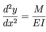
Three senior physics majors, Cody Borigo, Kevin Dougherty, and Darren Scott, are taking a special topics course in Strength of Materials, a standard course for mechanical engineering students. They intend to use the material as they pursue graduate degrees in mechanical engineering. As a break from working through the text (Applied Strength of Materials by R.L. Mott) they did a laboratory experiment to test one of the fundamental equations used to analyze the bending of beams:

where y is the displacement shown in the figure, and x is the displacement in the figure, measured from the orange clamp at the bottom. M is the bending moment (torque) experienced by the beam at the location x. E is

where the integral is over the
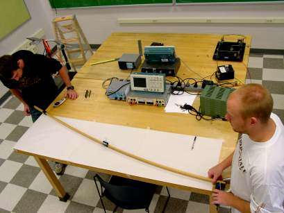
The differential equation predicts that when a beam is clamped (with the orange clamp) and pulled at its other end (with the black paper clip, as in the figure below, the deflection (y) of the beam as a function of distance from the clamp (x) is:

where F is the applied force (measured with the spring balance shown and later with an electronic force probe) and L is the length of the beam (in this case almost two meters).
The particular experiment shown uses two 2-meter sticks side by side. The moment of inertia in this case is:

where h is the height of the two stacked sticks, and b is the thickness, measured in the direction of y.
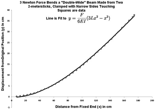
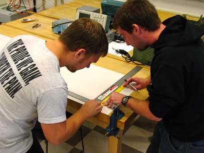
Cody, Kevin, and Darren applied a 3 Newton force to the end of the beam and traced the shape of the distorted beam on paper, producing a line as shown in the figure at the right. They also traced the figure of the beam when no force was applied.
They then measured

was taken as an adjustable parameter, and a small (0.24cm) constant term was added to account for a small y offset. The fit is shown below. The standard deviation between the experimental value of y and the fit is 0.25 cm, leading us to estimate the uncertainty in K at about 1%. With this estimate, we find


For the double-wide setup shown in the figure, the moment of inertia was calculated from the measured dimensions of the meter sticks to be
This led to an estimate for
E for red maple is listed as 1.13x10 10 Pa
Interestingly, when the sticks were clamped with wide sides together, the agreement was poor. This is presumably because the sticks are not welded together and the assumption that a cross section of the composite beam is undistorted by the bending fails. In

Bending the "double thick" beam combination

Measuring the y-displacement as a function of x.
-
Contact Information
Contact Number: 717-871-4297
Email: physics@millersville.edu