Experiment of The Month
Photoelectric Effect with 4 HeNe Wavelengths
The MU Physics Department does not claim to have invented these labs. The origin of these labs is currently unknown to us. Our labs do not have written instructions. In keeping with this spirit, the description given here will be brief and general. The intent is that each performance of the lab will be unique; in each nature will reveal a slightly different face to the observer.
This exercise has been done by our advanced physics students in research projects. It may become a regular part of our intermediate laboratory sequence. Partial support (the purchase of lasers) for this work was provided by the National Science Foundation's Division of Undergraduate Education through grant DUE-96-50912. Meron Wollie did the first tests with manual data collection in 1997. Keith Dailey developed the electronic circuits and automated data collection during the spring of 1998, for his Senior Seminar research project. In the summer of 1998, Michael Yonkunas added optical filters to improve our knowledge of the wavelength of light striking the photocell.
The photoelectric effect is regarded as a consequence of our modern understanding of quantum mechanics. Historically, however, the effect forced physicists to a non-classical view of the interaction between light and matter. It opened the doorway from a classical to a quantum understanding of physics. Because of
Students from other schools who are interested in repeating this experiment at Millersville should have their teacher contact Dr. Dooley of the Millersville University Physics Department.
Albert Einstein received the Nobel Prize, not for the theory of relativity, but for his analysis of the photoelectric effect. The relation between
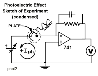
With the commercial development of helium-neon lasers for 612, 594, and 543 nm, in addition to the familiar 633nm wavelengths, the experiment has become accessible to students at the undergraduate, rather than the graduate, level. The experimental set-up used at Millersville is sketched in the figure, in condensed form.

The photocell is a glass evacuated tube, represented by the dotted circle. It contains a metal plate, shown as a curved line, and a collecting wire, shown as a dot. Light shines on the plate, electrons are liberated and some of them migrate to the wire, leaving the plate positively charged and the wire negatively charged. Rather than return across the vacuum, the electrons return to the plate following the low resistance path through the electronic circuitry provided. This flow of electrons is measured as the photocurrent.
Because the operational amplifier has a virtual ground at the inverting input, the photocurrent effectively flows in the loop indicated, including the photocell, the input terminals of the operational amplifier, and the adjustable emf. The adjustable emf supplies the "stopping potential" which opposes the photocurrent. The arrow indicates the direction of conventional current. A commercial power supply capable of zero output voltage was used as the adjustable emf.
In fact, three operational amplifiers were used. The first was wired as a current-to-voltage converter with capacitance in the feedback loop to reduce noise, the second was a summing amplifier to eliminate the dark current signal, and the third simply provided more gain.
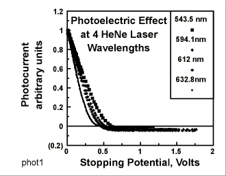
The voltmeter was a Vernier Software analog-to-digital converter. The voltage representing the photocurrent was recorded digitally as the experimenter varied the stopping potential. The graph represents data collected for the four wavelengths. (In the graph, only 1 out of every 50 data points collected is actually plotted, to save download time.)

For each wavelength, the signal voltage representing the current was divided by the signal measured when the stopping potential was zero. This is the reason that the apparent current begins at 1 for each wavelength on the graph. The graph shows convincingly that (in order to drive the photocurrent to zero) the stopping potential must increase if the wavelength decreases.
To make this qualitative observation quantitative, the stopping potential must be measured. The measurement is difficult because the measured current is
This current is "negative," flowing as if it were driven by the stopping potential. This current goes to zero when no light shines on the photocell. We suppose that it is a second photocurrent, caused by light striking the collecting wire, liberating electrons which migrate "
The back-current can be measured at high stopping potential. Then we know that the "forward" photocurrent is actually zero when the observed total current first becomes equal to the back current. This zero crossing is determined by first noticing that the photocurrent appears to fall linearly with low stopping potential. We fit a "least squares" straight line to the photocurrent plot, in the region between 60% and 20% of the initial current (from .6 to .2 on the graph). The "

We use the equation for this fit to find the stopping potential that gives a current equal to the "
One detail should be noted: The stopping potentials shown were actually calculated by calculating a second straight line fit; this time to the far right end of the curve where only the
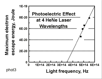
The 4 points clearly fail to fit a straight line. (The least-squares fit
The slope is the correct order of
The disturbing aspect of this motivation is that, if we did not know the accepted result, we might simply conclude that the data do not fit a straight line and consider the experiment finished. The tendency to continue experiments until they agree with the expected result is a common flaw for beginning physicists which, one hopes, is overcome by mature physicists.
This raises the somewhat troubling question of "How Experiments End." Peter Galison explores the question in a book
-
Contact Information
Contact Number: 717-871-4297
Email: physics@millersville.edu