Experiment of The Month
The Sound of Quality
The new science building has given us an interesting exercise in resonant vibrations. The wing that houses the physics offices and research labs also supports several tons of air conditioning equipment, about four meters above our heads. The flexible roof beam design responds to the natural vibrations of the three air conditioning units, both as a resonant object and as a vibration transmitter to other members.

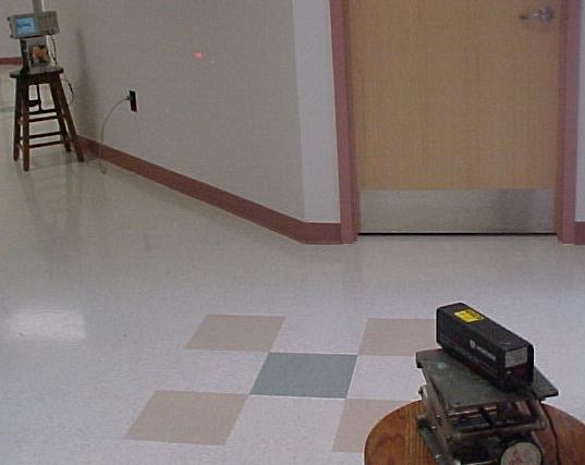
To quantify the qualitative observation that the acoustic ceiling panels were rattling in their tracks, and the floor "felt funny," we set up the system shown at the right. The laser shines on a detector which is about 2 meters distant. The detector measured a displacement of the concrete floor of about 0.1
Details of the
Measurements were also made using accelerometers with a sensitivity of 10 mV per g and a good response in the audio frequency range. These were mounted in three places, as indicated in the figures below:
- On the main frame of the air conditioner unit. The mounting blocks for the accelerometer are epoxied to the frame
- On the support just below the vibration isolation system. (The spring associated with vibration isolation is seen in the figure.)
- On a window sill in the same hallway that gave the 0.1 mm floor vibration. In the figure, our technician, Shawn Reinfried, points to the mounting block which is epoxied to the window sill.
(The accelerometers were acquired by the physics department for a 1996 senior seminar project by Shawn Reinfried and Dr. Nolan, on the dynamics of golf clubs.)
Outdoor Measurements
The figures below show the vibration spectra recorded using the accelerometers and MultiPurpose Lab Interface software. The top left figure shows the vibration spectrum for the probe mounted on the frame of the unit itself (the upper probe mount block in the figure above). It shows strong 60 Hz vibration and other vibrations at 30 and 120 Hz. The middle and right figures show two vibration spectra taken about 1 minute apart, on the roof side of the vibration isolators (the lower probe mount block in the figure above). In addition to reduced vibration strength, the second two figures
Indoor Measurements
The dominant frequency in the 0.1mm concrete floor vibration was approximately 60
The problem with this simple explanation is to decide how it can work. If a resonant object rings for a long time after being excited, it is said to be a "high quality" resonator. This happens when the frictional forces are
Frictional forces are said to "dampen" the vibrations, as a damp cloth will subdue a fire. The forces which cause vibrations to fade away are often called "damping" forces.
If there is any damping at all, theory and experiment show that
It has been suggested that the driver frequency (the vibrations from the air conditioner unit) is not constant, as the unit "hunts" to match its load. In that
The wide range of observed natural frequencies in the window sill is similarly hard to understand. The members which resonate at all these different frequencies should be hard to drive from a 60 Hz source, but there they are. The quality of the resonators must be high enough to ring and give the observed signal, yet low enough to allow excitation by the (mostly) 60 Hz driving vibrations. Evidently, the building resonant members have "
Steps are being taken to reduce the vibrations. The picture at the right shows vibration isolation coils being added to the supports for the pipes carrying coolant to and from the air conditioner units.S