Experiment of The Month
There's a Resonance in your Ear

In our Musical Acoustics class (Physics 205, required of MU music majors) we study both the mechanism for hearing and resonance in many forms. Physics majors interested in music work as laboratory assistants in this course.
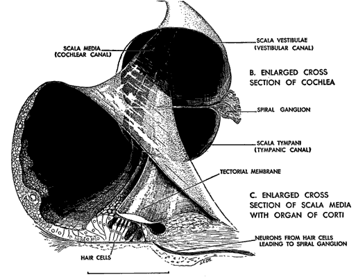
Your ear's job is convert sound into nerve impulses. After some impedance matching, the sound vibration travels down (from the top in the drawing ) a membrane that separates two canals. The membrane is called the basilar membrane. The drawing shows a cutaway of this membrane, the nerve cells that it supports, and the tectoral membrane which those nerves touch.
(The drawing was made by L.E. Delaney in about 1955.)
The nerve cells are touch sensitive. The simplest model for hearing is that different pitches set different parts of the basilar membrane into vibration. The touch cells report to the brain the location and nature of membrane vibration. The brain interprets that location as a pitch. A more detailed description is given here: HyperPhysics Article.
This article is about building a mechanical model of this hearing mechanism. We have a device that vibrates large in different locations; the location varying with the pitch. It is made with a family of pendulums, each of different lengths. I first became aware of such a device by reading the wonderful book "Vibrations and Waves" by A. P. French.

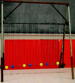
MU physics major Matt Kurman (class of 2004) built the set of 11 pendulums which mimic the "place" model of hearing. 10 of the pendulums are made of string and tennis balls. The string runs in the left side of the ball and out the right. Each end of the string are threaded through a vertical hole in the support rod (figure 2pendulumrig) so that each ball is suspended from two points. This suspension makes it easy for the balls to swing forward and back and hard for them to swing side to side.
The 11th pendulum is at the right end of the support rod. It has a steel shaft welded to the support rod, with 4kg of steel weights at the bottom for a bob. The support rod is mounted in bearings (on the left and right ends) that let it rotate so that the heavy pendulum swings freely forward and back. When set into motion, the heavy pendulum will swing for a minute or two.
The tennis ball pendulums are all of different length, with the longest at the left end. The red ball nearest the left end is almost the same length as the steel pendulum. When the steel pendulum swings, the bottom of the support rod rocks the top end of the tennis ball pendulums back and forth. The tennis balls respond by beginning to swing. Because of this effect, the steel pendulum is called the "drive pendulum."
The period (T) of a pendulum is determined by its length (from the pivot to the tennis ball). The formula is
T = (2 pi)(L/g)(1/2)
where L is the length of the pendulum and g is the gravitational field strength (the same as the acceleration of a freely falling object).
 The red ball closest to the left end has the same natural period as the drive pendulum because it has the same length. This causes the red ball to swing most enthusiastically in response to the motion of the drive pendulum.
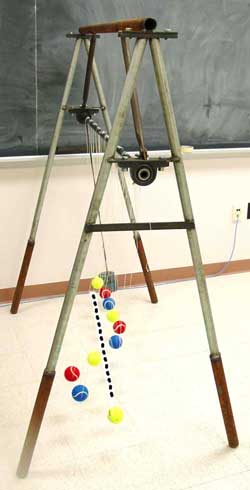
The figure at the right shows a side view of the rig with the pendulums in motion.
The heart of the system is the "A" frame made with the galvanized (bright) steel. The bearings for the support rod look like upside down pillows, mounted on a short cross piece. The lower (rusted) legs set the height so that the pendulums can be about a meter in length. The upper (rusted) bar and cross braces are to add stability to the rig. The upper frame can be unbolted from the A-frames so that the system can be transported.
The dotted line indicates the resting position of the pendulums. The driver is the right of its rest position, swinging towards rest, as are all the "too short" pendulums. The red pendulum and the longer ones are at the left of their rest positions.
The red ball is said to be "at resonance" or "in resonance with the driver."
The balls farthest from resonance display practically no motion - they just don't respond much to a driver that is so far from their natural period.
The figure is representative: The short pendulums follow along with the driver for their motion. They are said to be "in phase" with the driver. The longest pendulum (the yellow one) are "out of phase" with the driver; swinging right when the driver swings left.
This effect might account for the ear's ability to discern very small differences in sound frequency (pitch).
It is clear from figure that the exact location of maximum swing is hard to identify. The blue ball swings almost as much as the red ball. On the other hand, it is very clear that the red ball and its neighboring yellow ball are behaving very differently. If the pendulum model for hearing is correct, it may be that the ear detects differences in motion, rather than sizes of motion. Perhaps it identifies the location in-between two places that oscillate in opposite directions.
The motion of the red ball that is at resonance (as well as that of its blue neighbor) requires more discussion. How can it be that the most responsive ball is at its maximum displacement when driver is at its resting position?

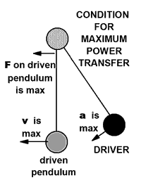
The answer has to do with delivering power from the driver to the resonant pendulum. The figure at the right shows the driver pendulum and the resonant pendulum at a different instant in the motion. The driver is now at its maximum position and the driven (red) pendulum is at the bottom of its swing, going at its maximum speed.
The drive pendulum turns the support rod clockwise as it swings down. The bottom of the support rod moves to the left while the driver swings down to the left. That leftward motion pulls to the left on the driven (red) pendulum. This is the set up for the driver to do maximum work on the red pendulum.
Technically, the work on the pendulum is equal to the product of the force on it times the distance moved.
The driver (and the support rod) are experiencing maximum acceleration at this time. This large acceleration is required to stop the rightward swing of the driver, turn it around, and start it back to the left. The support rod forces the top of the red pendulum string to accelerate with it, and that string in turn exerts a leftward force on the red ball.
At the instant shown, the force by the driver on the red ball is maximum, and the red ball is moving fastest to the left. During this time, the driver is doing maximum work on the red pendulum because both the force and the displacement in a small time interval are maximum. Because it experiences the greatest work, the red pendulum acquires the largest amount of energy. It swings with the greatest amplitude.
For a movie showing more detail of the motion, click here for movo1853.