Experiment of The Month
Low Temperature Gold Film Resistance
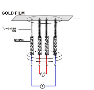
 This is a progress report, based on the senior seminar project of Andrew Jones. He measured the resistance of thin (about 100 nm) gold films evaporated onto polyethylene transparency plastic. He used a four-probe method, as sketched in the figure at the right.
A power supply (labeled "A") drives a fixed current between the two most widely-spaced pins, and a voltmeter (labeled "V") measures the potential difference between the inner pin pair. The measured potential difference is independent of any contact potentials that might be present where the current supply pins contact the gold film.
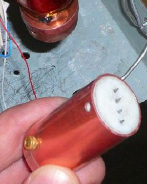
The pins are pressed against the gold film with springs. The purpose of the springs is to compensate for thermal contraction of the pins as the assembly is cooled down to 7 degrees above absolute zero. The springs and pins move in holes drilled in a

The plastic that supports the gold film is pressed against a copper block at the top of the sample chamber. This block, in
Mr. Jones and Drew Pulsifer worked together to produce this sample chamber. It has the virtue of enclosing the sample in a copper jacket to shield against radiant heat entering the refrigerator. The copper jacket absorbs this heat and shunts it to the cold
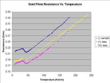
Mr. Jones' resistance data are shown in the figures below. They show a linear decrease in resistance as the temperature is decreased from room temperature. This is consistent with the following simple ideas: The atoms vibrate like "Einstein oscillators" about their "home position." Their energy of oscillation is
From the point of view of a traveling conduction electron, the vibrating atoms map out a circular area whose size is measured by the square of the amplitude, A2. The probability of an electron colliding with the atom is proportional to that area, called the scattering
In the classical theory of electrical conduction, the resistance is proportional to 1/t, and thus the resistance is proportional to the temperature.


The purple and the blue data sets were taken on samples cut from the neighboring sections of the same large sheet of film. For the blue data, the current flows in the direction that was horizontal during evaporation. For the purple data, current flows in the direction that was vertical during evaporation. The intent is to investigate the anisotropy in electrical resistivity that is caused by details of the film preparation.
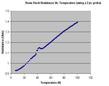
The resistance becomes more interesting below 50Kelvin. There is a bump in both gold films and a piece of brass shim stock, used for control. Both materials show more curvature below this bump. The fact that a bump is present in the brass suggests that the bump is not characteristic of the material. Non-linear resistance is to be expected at low temperatures, as impurities and dislocations begin to dominate the scattering of conduction electrons.
-
Contact Information
Contact Number: 717-871-4297
Email: physics@millersville.edu